elevation view engineering drawing
What are Elevation Drawings. 112 and it will be apparent that the projected length of the line DF in each of the views will be equal in length to the diagonals across each of the rectangular faces.

Engineering Drawing Diagram Floor Plans Drawings
An elevation is a drawing that shows the front or side of something.

. STEP 03 Rotate and relocate the section view c-c from the inserted image to match the boundary of the elevation. From the view of the other two sides it will stay at one level. The Procedure for Drawing an Elevation Plan 1.
It could be that you only need a set of four elevations or you may need many more. Most architects use a four-dimensional view when creating the elevation drawing north south east and west. Elevation view are used to fully describe an object however in some instances more than one elevation view is needed.
One such standard convention is called GD T. An isometric view of a rectangular block is shown in Fig. Thus you see the tops of everything but you cannot view the front side or back of an object.
5 Side Views When the observer looks at the object from side ie from his left-hand side or right-hand side the view obtained is called. The PID example uses some PIDs such as tank mixer column plate tower and onion tank equipments. An elevation gives you the chance to see everything from the other viewpoints.
Divide the end elevation into 30 divisions. For a shed or gable roof with eaves the roof on two sides will drop lower than where it connects with the wall. If an elevation view is named the North Elevation it means that the drawing is looking at the facility from the north direction as specified by the North arrow on the plan view.
Plan Section and Elevation are different types of drawings used by architects to graphically represent a building design and construction. 2-21 is an example of this type of drawing. FV is seen on the VP.
You will need to understand the concept of elevation and will draw only interior elevation. 4 When the observer looks at the object from above the view obtained is called top view TV or plan. It is usually created in accordance with standard conventions for layout nomenclature interpretation appearance etc.
A little tricky hey. The above elevation drawing is drawn with the Edraw Max software. TV is seen on the HP.
The purpose is to convey all the information necessary for manufacturing a product or a part. An engineering drawing is a subcategory of technical drawings. The engineering drawing is a type of technical drawing created within the technical drawing discipline and is used to define the requirements for engineered items.
Place the floor plan directly above the space where the elevation is to be drawn. STEP 01 Decide an elevation view. The external elevation will show a vertical surface or plan seen from a perpendicular point of view.
Using the cam graph as the center line for each position of the roller draw 14 mm diameter circles as shown. Ad Access The Best Most Comprehensive Commercially Available Elevation Data. Imagine the top and sides of an object.
A plan drawing is a drawing on a horizontal plane showing a view from above. Pipe Drafting and Design Fourth Edition 2022. An elevation is a drawing made with lines and shading on paper or canvas to display the appearance of an object when viewed from the side.
A short series of lectures on Engineering Drawing as Part of ENGG1960 By Paul Briozzo. Indicate the bottom of the footer and draw a horizontal line. The elevation view is the view from one side of the object.
Sectional views in engineering technical drawings. Below is an example elevation drawing showing the location of process equipments in relation to existing structures and ground level. Project all points down to the free space.
The view of the building that you are seeing is called the north elevation. Here is a plan drawing. Plans and elevations are 2D drawings of a 3D shape.
The plan view is the view as seen from above the ob- ject looldng down on it or the top view. Its simple enough but its extremely important that you get this distinction right. Gaskets seals Do not show.
The perspective in an elevation drawing is flattened. How to Identify Plan Elevation and Section in a Drawingfor clear understanding watch my videoShare Support SubscribeTwitter. STEP 02 Draw outline of the elevation by using xline to draw the boundary of the elevation.
Features that cannot be seen by hidden detail Cutting plane removes part section is what is left Cross hatching ois at 45 equispaced Centrelines often used for cutting planes Very thin sections not hatched eg. Elevations are often used to show the configuration of beams floors walls and other structural components within a building as well as their relationship to one another. Download Full Software Package and View.
Three orthographic views in firstangle projection are given in Fig. Underneath the front elevation draw a development of the cylindrical cam surface and on this surface draw the cam graph. An elevation drawing which is part of construction documentation includes the first angle projection of all the parts of a structure as viewed from a specific direction.
This makes understanding the drawings simple with little to no personal interpretation. It is basically what you see while looking South when you are standing North of a particular building. A floor plan by contrast shows a space from above as if you are looking down on the room from the ceiling.
Up to 5 cash back 3 PLANS ELEVATIONS AND PARALINE PROJECTIONS Before attempting to construct perspective views it is worth reviewing how plans and elevations are derived. The corners of the block are used to position a line DF in space. A plan is a scale drawing showing a 3D shape when it is looked at from.
Set out the cylinder blank and the end elevation as shown. Engineering Drawing Basics Explained. An Elevation drawing is drawn on a vertical plane showing a vertical depiction.
The exterior walls to be represented by the elevation should be facing down toward the elevation. - Selection from Basic Perspective Drawing. For example the building may have courtyards a complicated floor plan that requires more communication of the elevations.
Engineering drawings use standardised language and symbols. A Visual Approach 5th Edition Book. The following texts are the property of their respective authors and we thank them for giving us the opportunity to share for free to students teachers and users of the Web their texts will used only for illustrative educational and scientific purposes only.
View obtained is called the front view FV or Elevation. A section drawing is also a vertical depiction but one that cuts. Sectional views in engineering technical drawings.
To draw the roof for each elevation view first consider whether your roof will overhang and drop below the exterior wall on the elevation plan you are currently drafting.
Engineering Drawing And Sketching Mechanical Engineering Isometric Drawing Technical Drawing

Orthographic Projection Orthographic Projection Orthographic Drawing Elevation Drawing

Sectional View Orthographic Drawing Wooden Sofa Set Technical Drawing
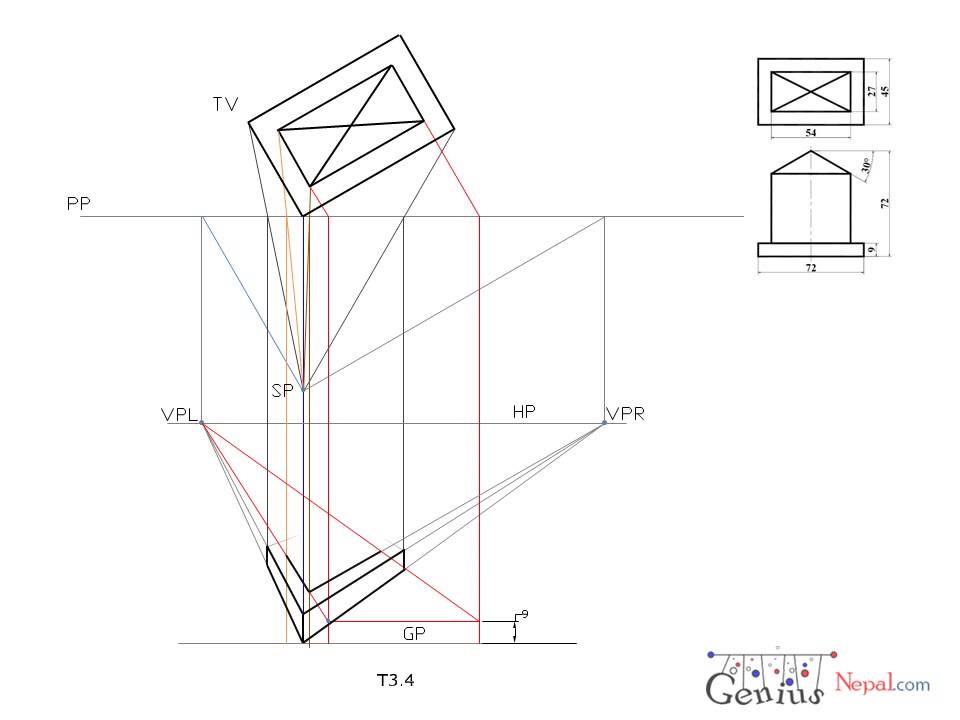
Engineering Drawing Tutorials Perspective Drawings With Front And Side View T 3 4 Youtube Perspective Drawing Drawing Tutorial Perspective

Engineering Drawing Tutorials Perspective Drawings With Front And Side View T 3 4 Youtube Perspective Drawing Drawing Tutorial Perspective

Plan Elevation And Sectional Detail Superstructure Of Bridge Layout Autocad File Bridge Construction How To Plan Detailed Drawings

Projection Drawing A Drawing That Represents A Solid Shape Or A Line As Seen Form A Particular Direction Perspektif Cizimler Cizim

Building With Elevation Details In Autocad Mosque Design Mosque Autocad

Orthographic Projection Orthographic Projection Orthographic Drawing Elevation Drawing

Orthographic Drawing Kervin Swandi Kelas 1 Kelompok 5 Orthographic Drawing Orthographic Projection Architecture Drawing

Orthographic Drawing Orthographic Drawing Technical Drawing Geometric Drawing

Orthographic Draw Clases De Dibujo Tecnico Tecnicas De Dibujo Clases De Dibujo

Technical Drawing Elevations And Sections Technical Drawing Construction Drawings Drawing Sheet

Pin By Dorian On The Nerdy Side I Love Of My Life Orthographic Projection Isometric Drawing Exercises Isometric Drawing

Simple Projection In Perspective Drawing Fundamentals Perspective Drawing Perspective Drawing Architecture Perspective

Multi View Analysis Of A Third Angle Orthographic Projection Orthographic Projection Orthographic Drawing Isometric Drawing

Streetlight Detail Section And Elevation 2d View Layout Autocad File Street Light Autocad Layout

Comparison Of Graphical Projections Axonometric Projection Wikipedia Orthographic Projection Isometric Isometric Drawing

Chapter 3 Plans Elevations And Paraline Projections Book Orthographic Drawing Technical Drawing Autocad Isometric Drawing